Your cart
There are no more items in your cart
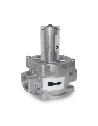
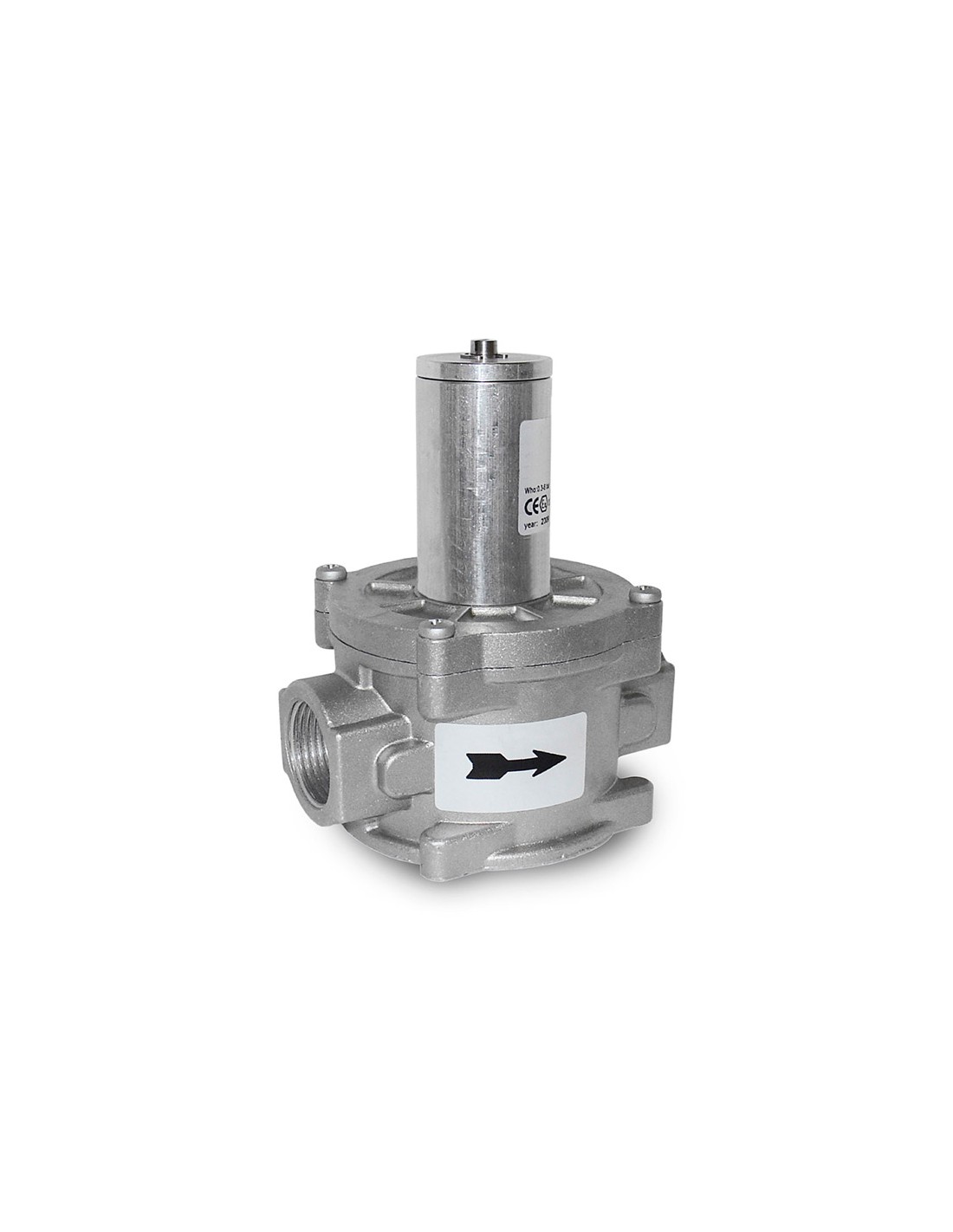
Relief valve max 1bar
VS202.05
Last items in stock
Tax included
Relief valve with spring control and automatic drain Dn 25 p.max 1bar pressure range 30÷110mbar
Relief valves are safety devices that discharge a certain quantity of gas to the outside when the pressure at the control point exceeds the calibration pressure (bubble burst pressure) due to non-lasting events such as the closing of valves of interception in a very short time and/or overheating of the gas with zero required flow rate. the discharge of the gas outside can, for example, avoid the intervention of the blocking devices for transitory causes not deriving from damage to the reducers. Obviously the quantity of gas discharged depends on the extent of the overpressure compared to the calibration. The operating principle of these safety devices is based on the comparison between the thrust on the diaphragm or piston deriving from the pressure of the gas to be controlled and the thrust deriving from the calibration spring. Obviously, the weight of the mobile unit, the static and dynamic residual thrusts on the armed pad also intervene in this comparison. When the thrust resulting from the gas pressure exceeds that of the spring, the shutter is raised resulting in the discharge of a certain quantity of gas; otherwise the shutter is released and closes the valve seat under the pressure of the pressure of the gas to be controlled alone and not of the calibration spring. In this way, damage to the reinforced pad due to incorrect adjustments of the calibration adjustment nut is avoided.
Marking and Regulatory References Degree of Protection:
Compliant with Directive 97/23/EC (PED Directive) Compliant with Directive 94/9/EC (ATEX Directive) Rp threaded connections: according to EN 10226 • PN 16 flanged connections: (DN 25 - DN 32 - DN 40 - DN 50) according to ISO 7005
Material
Relief valves are safety devices that discharge a certain quantity of gas to the outside when the pressure at the control point exceeds the calibration pressure (bubble burst pressure) due to non-lasting events such as the closing of valves of interception in a very short time and/or overheating of the gas with zero required flow rate. the discharge of the gas outside can, for example, avoid the intervention of the blocking devices for transitory causes not deriving from damage to the reducers. Obviously the quantity of gas discharged depends on the extent of the overpressure compared to the calibration. The operating principle of these safety devices is based on the comparison between the thrust on the diaphragm or piston deriving from the pressure of the gas to be controlled and the thrust deriving from the calibration spring. Obviously, the weight of the mobile unit, the static and dynamic residual thrusts on the armed pad also intervene in this comparison. When the thrust resulting from the gas pressure exceeds that of the spring, the shutter is raised resulting in the discharge of a certain quantity of gas; otherwise the shutter is released and closes the valve seat under the pressure of the pressure of the gas to be controlled alone and not of the calibration spring. In this way, damage to the reinforced pad due to incorrect adjustments of the calibration adjustment nut is avoided.
- Marking and Normative References
- See description
- Fluids
- Non-aggressive gases of the 3 families (dry gases)
- Conn.IN
- DN25
- Conn.OUT
- DN25
- Max pressure
- 1Bar
- Attack
- Threaded
- Operating temperature
- -15 ° + 60 ° C
- Pressure range
- 30 ÷ 110mbar
Tap to zoom